Accurate installation drawings to ensure the stability of maritime breakwaters
CLAS prepares highly detailed installation drawings for the placement of single-layer artificial concrete blocks used in breakwaters, groynes, and breakwaters.
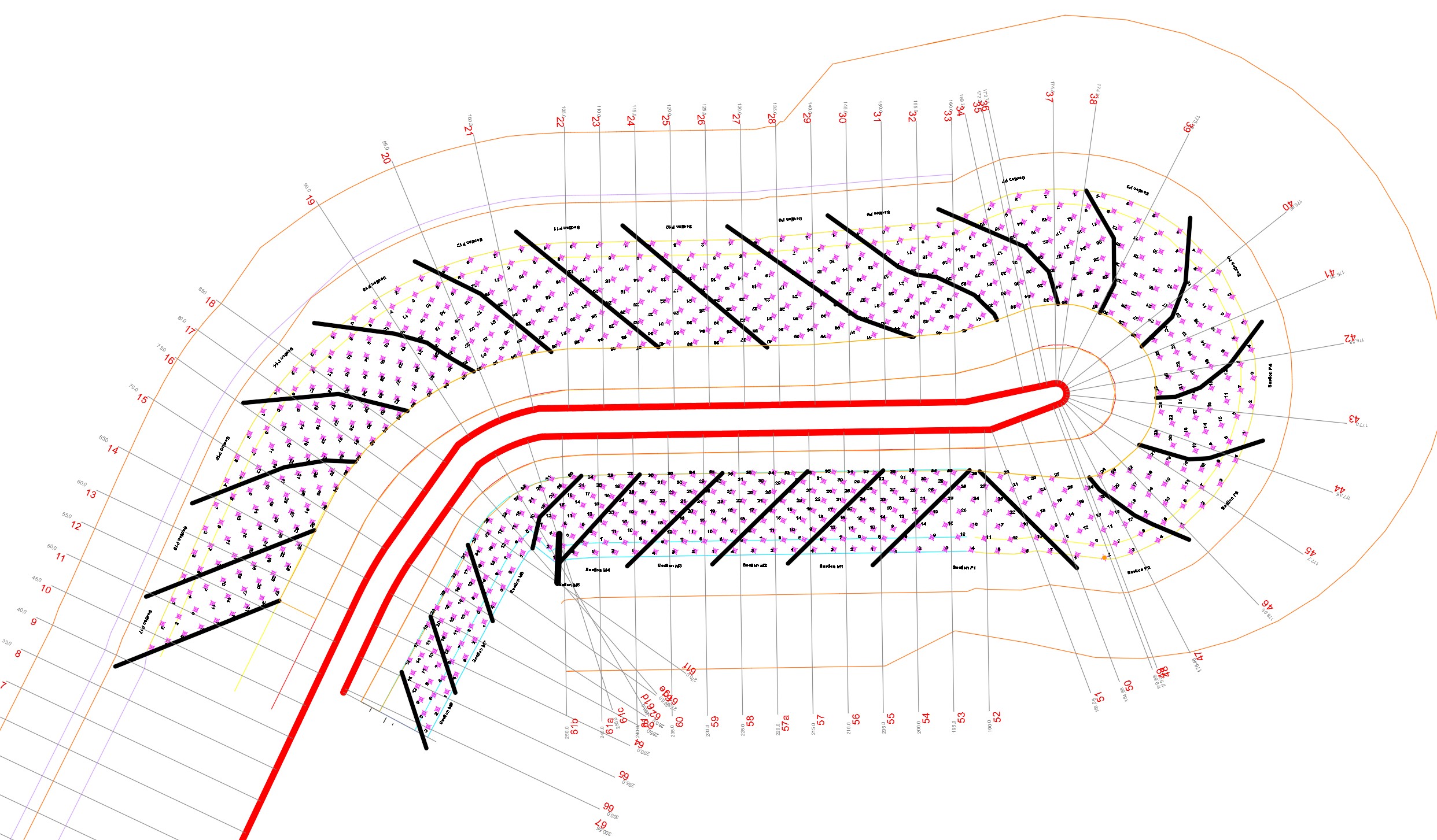
These technical documents are a key step in the construction and certification process: they define the position and the interlocking density of each block, ensuring the hydraulic stability and compliance of the structure.

An exclusive service based on field experience
Since 2021, CLAS has been preparing installation drawings for the placement of the royalty-free BS1, BS2, BS3 and BS4 blocks under the BREAKWATER SOLUTION™ brand.
Each drawing is tailored to the actual geometry of the structure (profile, bathymetry, curvature).
CLAS has acquired unique experience by integrating real placement results observed on site into the design of the drawings, making it possible to correct the gaps between theory and construction reality.
Based on the interlocking capacity specific to each artificial block shape, the installation drawings produced by CLAS have reached an unmatched level of refinement, providing contractors with a high degree of confidence in constructability and ensuring the mechanical robustness of the armour layer.
Installation drawings compliant with technical reference frameworks
CLAS installation drawings are prepared in accordance with the applicable technical reference framework:
CLAS technical reference framework for CORELOC, BS1, BS2, BS3 and BS4 blocks.
They also comply with the recommendations of the Rock Manual and the CEREMA Rock Armour Guide, as well as with the CCTP requirements of French public procurement contracts, ensuring compatibility with international standards and recognized coastal engineering practices.
A specific feature of our installation drawings is that, for all block types, the minimum required placement density is 98%. We have long ceased to apply placement densities below 98%, even where the license agreement under which we operate would allow it.
Design stages of an installation drawing
Analysis of the block’s interlocking capacity,
Analysis of site data: bathymetry and project geometry.
Definition of the nominal installation plan with identification of each block.
Optimization of the block layout to achieve the required placement density (98–105%).
Technical validation prior to release to the construction site.
Each plan is delivered in AutoCAD and PDF formats.
Installation assistance
CLAS also provides technical assistance during on-site installation, ensuring the correct implementation of the installation drawings.
Our inspectors supervise:
the geometric compliance of the seating layers,
the actual interlocking density,
and the validation of each armour layer section prior to certification.
This integrated approach — design, supervision, certification — ensures full technical continuity and complete traceability for the owner.
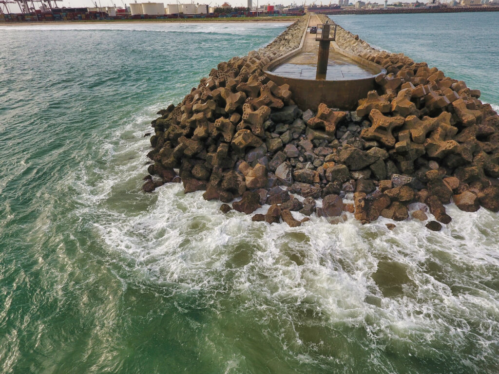
This breakwater benefited from CLAS assistance from the preparation of the installation drawings through to final certification.

This breakwater did not benefit from CLAS assistance from the preparation of the installation drawings through to final certification.